Signed-off-by: Yilin Sun <imi415@imi.moe> |
||
|---|---|---|
| assets | ||
| libraries@2b63f6fc6e | ||
| .gitignore | ||
| .gitmodules | ||
| LICENSE | ||
| Pudding_MPyATE.kicad_pcb | ||
| Pudding_MPyATE.kicad_pro | ||
| Pudding_MPyATE.kicad_sch | ||
| README.md | ||
| sym-lib-table | ||
README.md
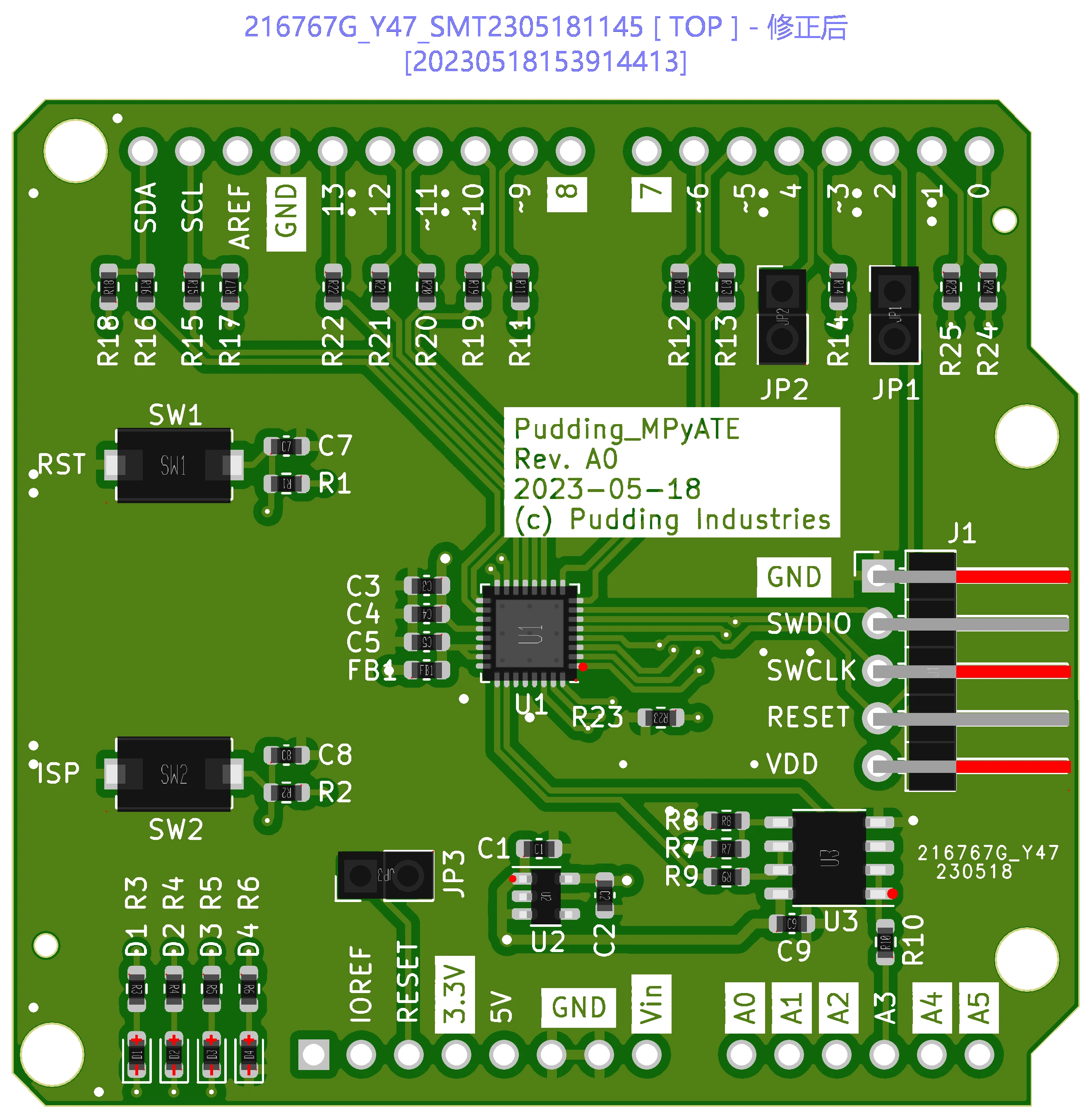
MicroPython ATE Shield
Why
This board is created trying to solve the following problem in MicroPython project:
What if the code compiles, but does not work as intended?
So an idea came up by @robert-hh, that we can make these testes automated with a "shield" (See here)
Some peripherals CAN be verified by connecting to itself, such as UART and GPIO, while others can't be easily verified without some on-board devices like sensors or EEPROMs. So instead of mounting all sensors on a board, a cheap MCU is used to act like some peripherals, which can produce controllable and repeatable results to DUT.
This board can be used to verify the following peripheral drivers:
- ADC
- UART
- SPI
- I2C
- PWM
- GPIO
LPC804
Why LPC804?
- Cheap enough
- Fully 5V IO tolarent
- Has an DAC(!)
- Switch Matrix
